HMI and industrial PC
Select a job, machine, box and recipe. See requested and confirmed tools, calibration, fit quality, support condition and alarms. Requests go through the cell PLC.
 ENGINEERING← Back to simulator
Source dimensions, metrology and control demonstrations supporting the interactive simulator.
The original sampled geometric checks reported no unintended contact in 26,481 mobile, 31,873 fixed-POC and 6,565 carrier configurations. These are discrete geometric checks; they do not establish continuous clearance, force limits, quartz stress or machine safety.
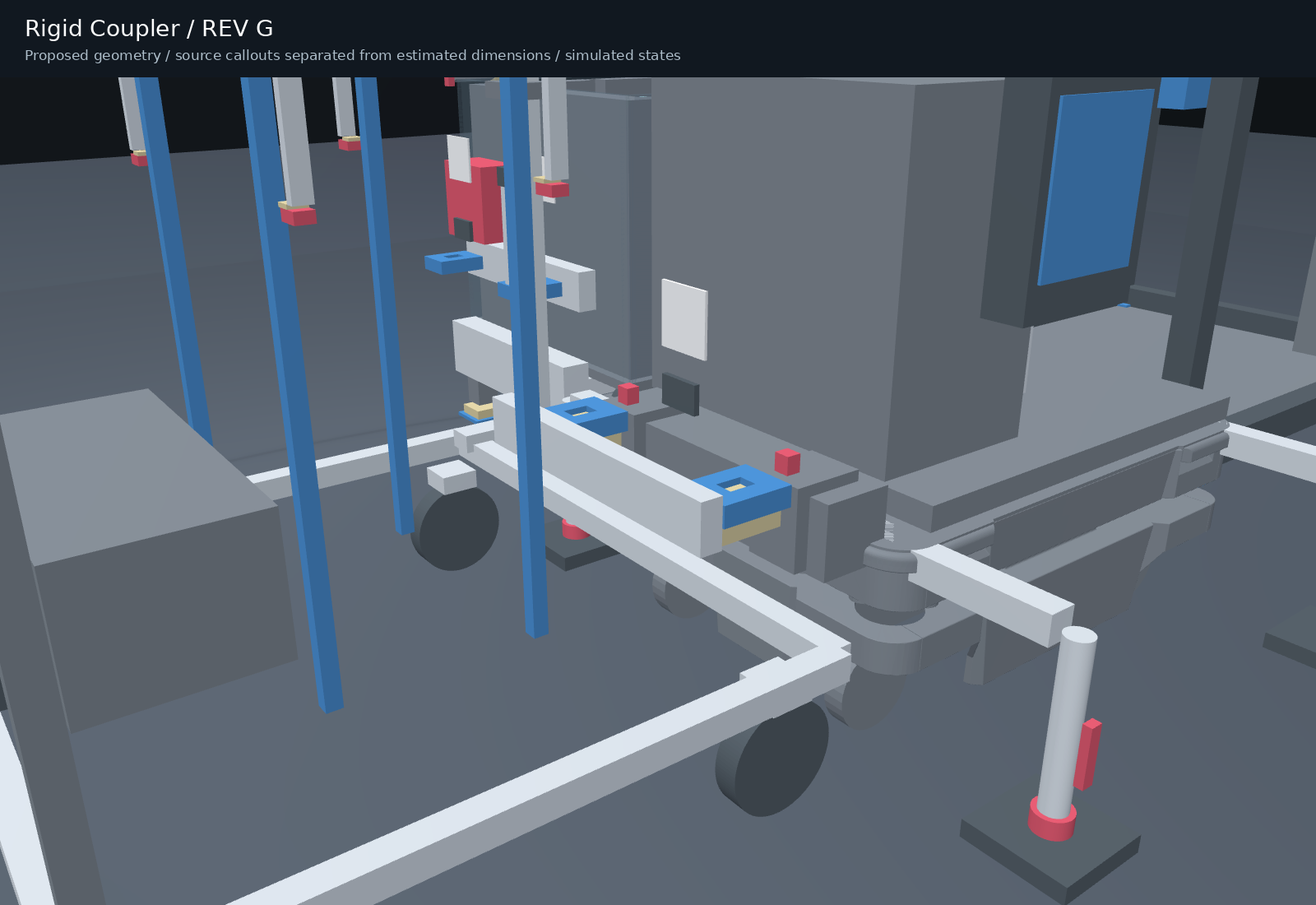
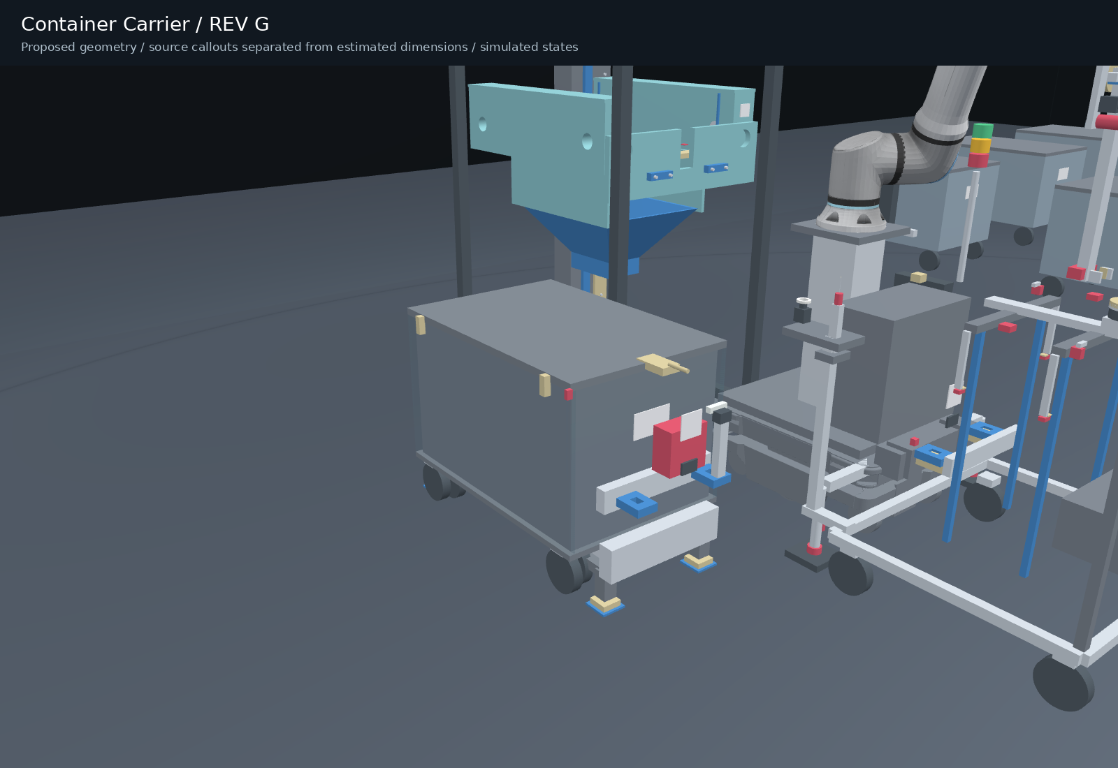
The full mission joins the carrier handover to the matching supported installation pose. Its playback uses the original review samples; it does not generate new robot commands or apply measured offsets.
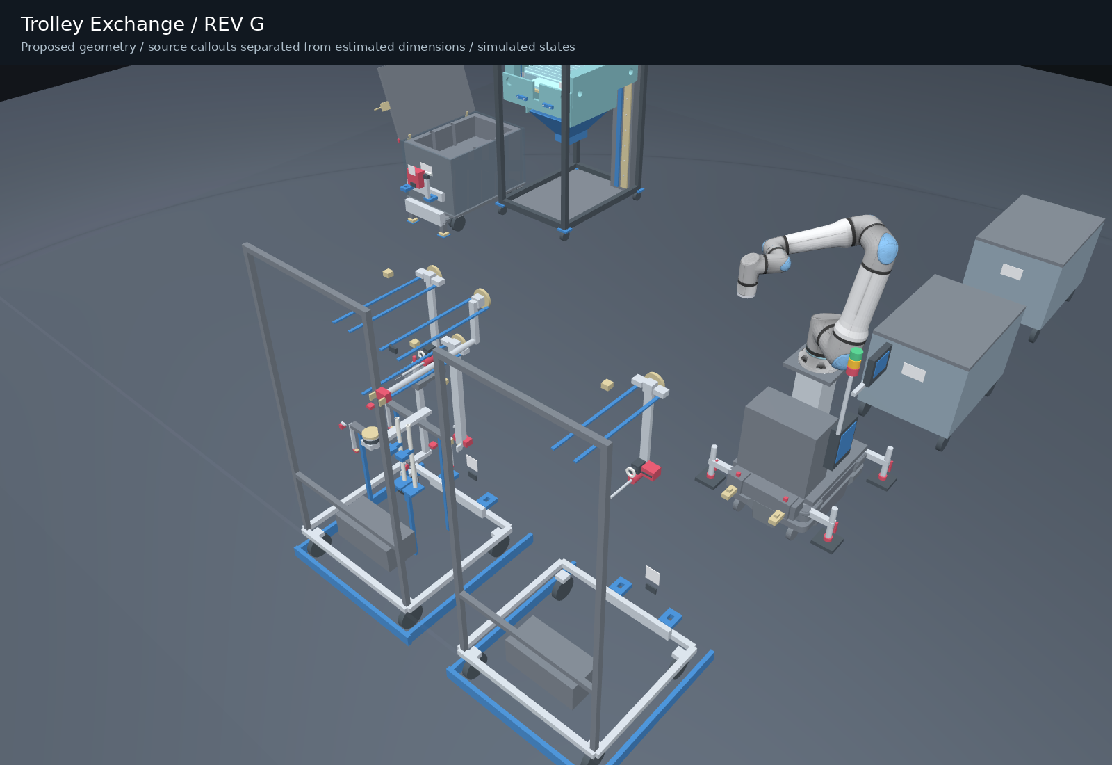
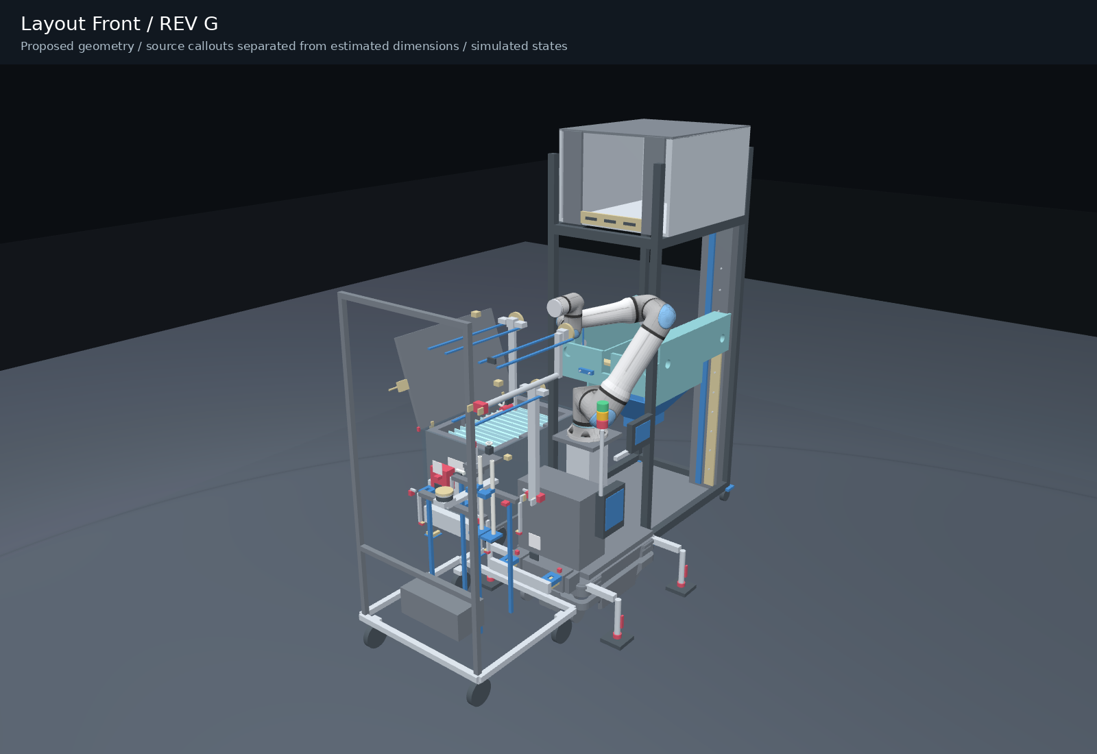
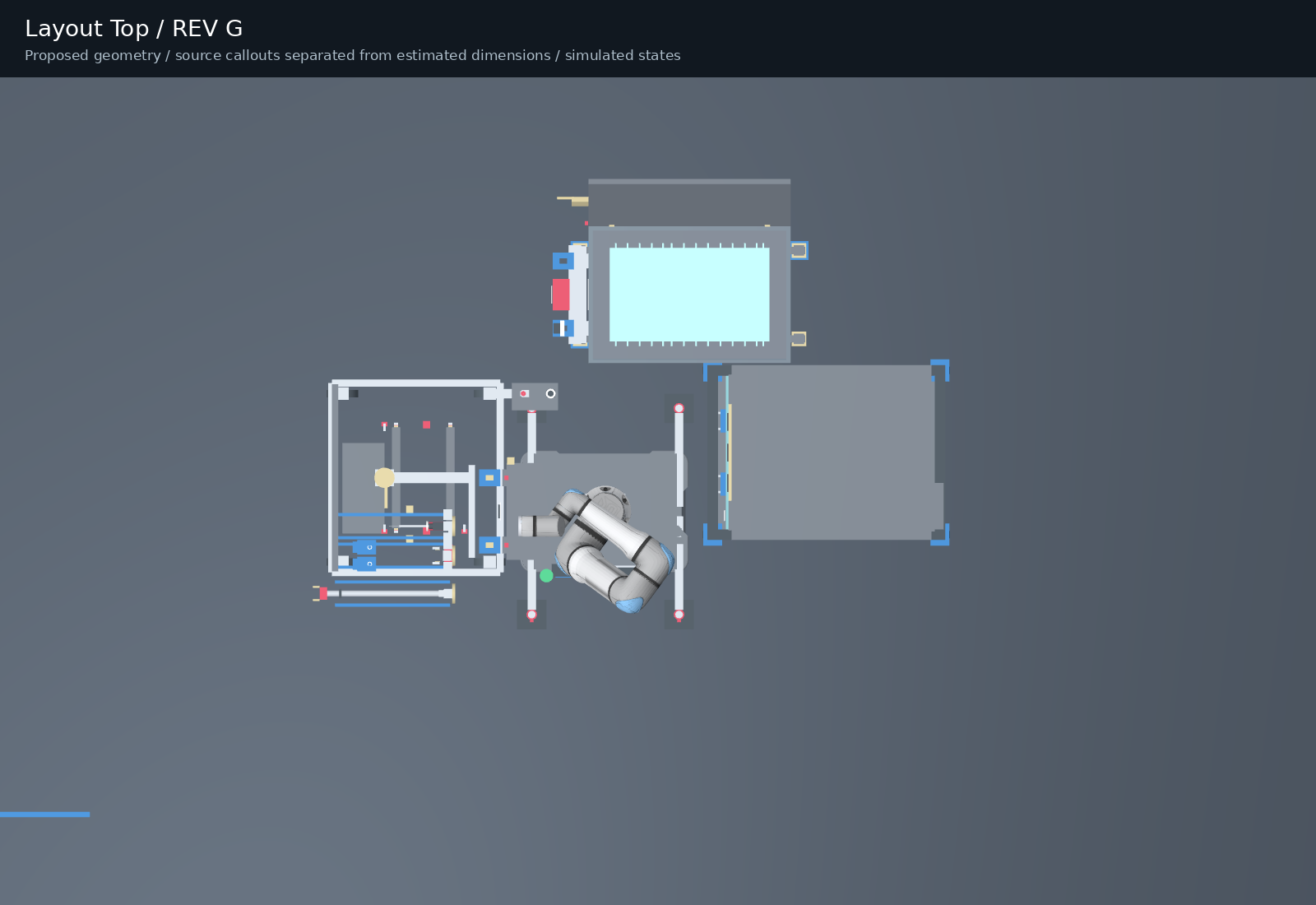
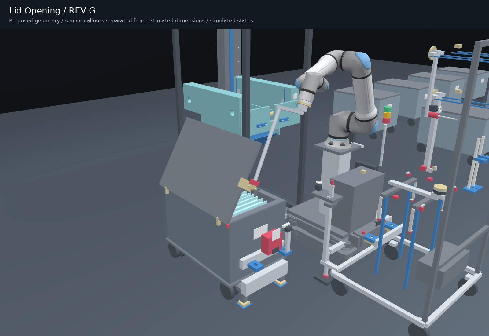
UR30 visuals use the Universal Robots description meshes. The MiR250 is a community reference model. The chamber and machine use annotated customer dimensions and identified estimates. Pin/hole diameters, coupler approval, payload, stability and ISO 7 qualification are open items.
Two temporary guides are optional. Their install/remove sequence is a planning study; no corresponding robot path or collision result was recovered.
02 / CUSTOMER SOURCE
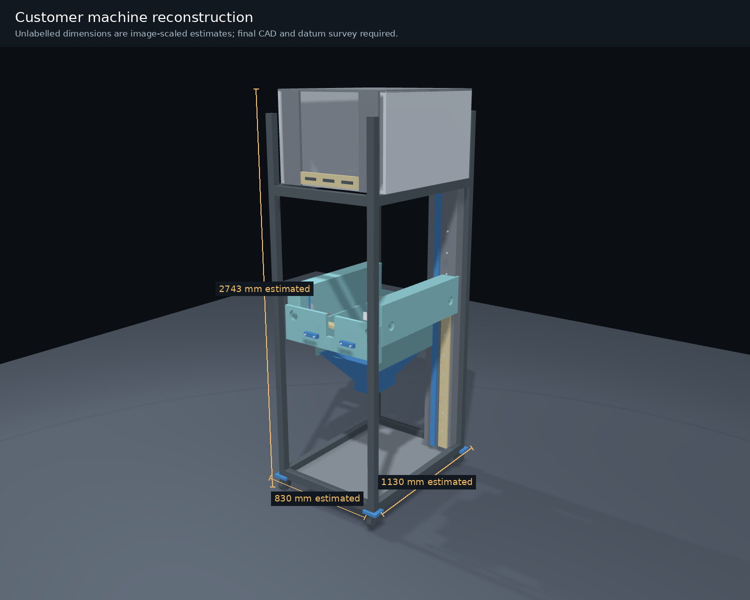
All ten slides were reviewed. Slides 7 and 8 also contain three embedded STEP files: the existing tong and left/right installation guides. The machine outline is reconstructed; only annotated dimensions are source dimensions.
| Feature | Model value | Evidence |
|---|---|---|
| Type 1 quartz | 759 × 490 × 159 mm fin envelope | Customer slide 5 |
| Type 1 body | 113 mm external height; 88 / 433 mm internal opening | Customer callouts; remaining wall dimensions inferred |
| Tubulation | Ø34; 355 mm upper datum to tip | Tube tip −219 mm relative to fin bottom in this reconstruction; 378 mm total height |
| Machine access | 850 / 550 / 1250 mm | 850 window; 550 transverse interpretation and 1250 seat datum require confirmation |
| Pin / guide spacing | 700 / 310 / 450 / 230 mm | Source annotated views; pin Ø8 and hole Ø10 are explicit assumptions |
| Machine frame envelope | 830 × 1130 × 2743 mm nominal | Approximate image-proportion reconstruction, not a toleranced machine drawing |
| Installation guides | 400 mm CAD length | Customer guide reference retained; robot-handled sleeves and mounts are proposed geometry |
| Floor | 10 kN/m² | Distributed rating; concentrated foot loads require separate approval |
03 / METROLOGY AND HANDLING
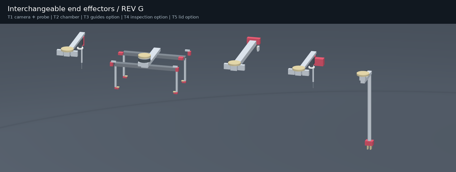
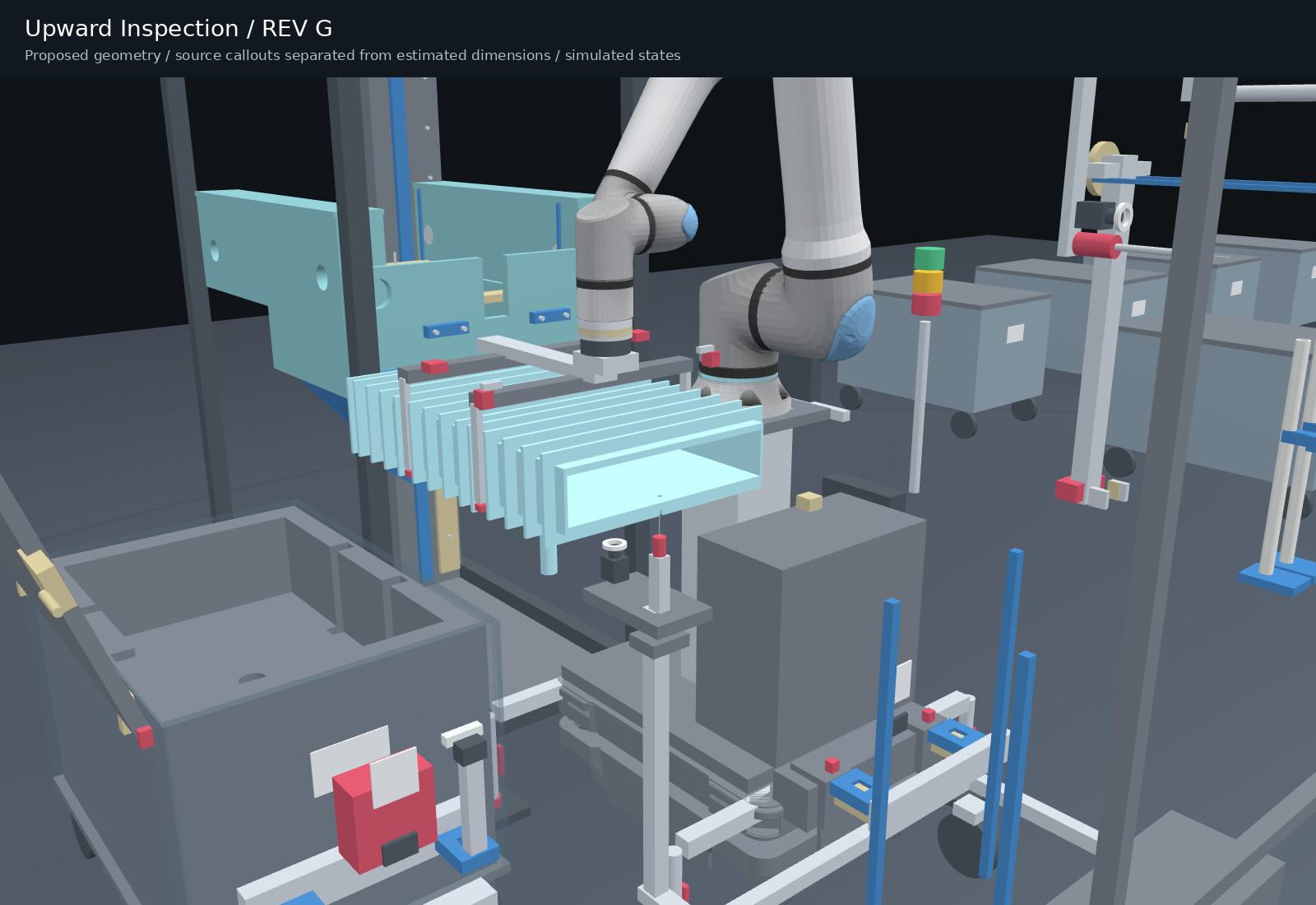
T1 measures before exchange. The upward camera and probe stay fixed on trolley A while the robot presents the held chamber to them. A rigid pose correction cannot repair a mismatched hole pattern.
| Condition | Control response |
|---|---|
| Chamber stuck in foam | Excess extraction force, load imbalance or abnormal moment → retained HOLD. No harder pull. |
| Vision / probe disagreement | Hold; inspect identification, datums and calibration. Measurement diversity does not automatically establish safety redundancy. |
| Final pin engagement | Square approach; slow vertical seating with independent force/torque monitoring. No forced search. |
| Release | Confirm all three seats and load handover; unload pads before opening. |
Enter three identified, calibrated centres in mm, in the order front, rear-left, rear-right. This synthetic example assumes a 35 mm pin-tip-to-seat offset and a 0.2 mm pattern check limit. These values are illustrative, not accepted process tolerances.
This is a separate offline calculator. Its result never changes the recorded robot path.
CONTROL ARCHITECTURE / REV G
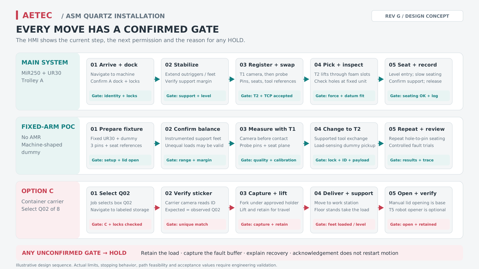
The operator interface shows the active step, the blocking condition and the evidence needed to continue. The cell controller owns the sequence and verifies each device response.
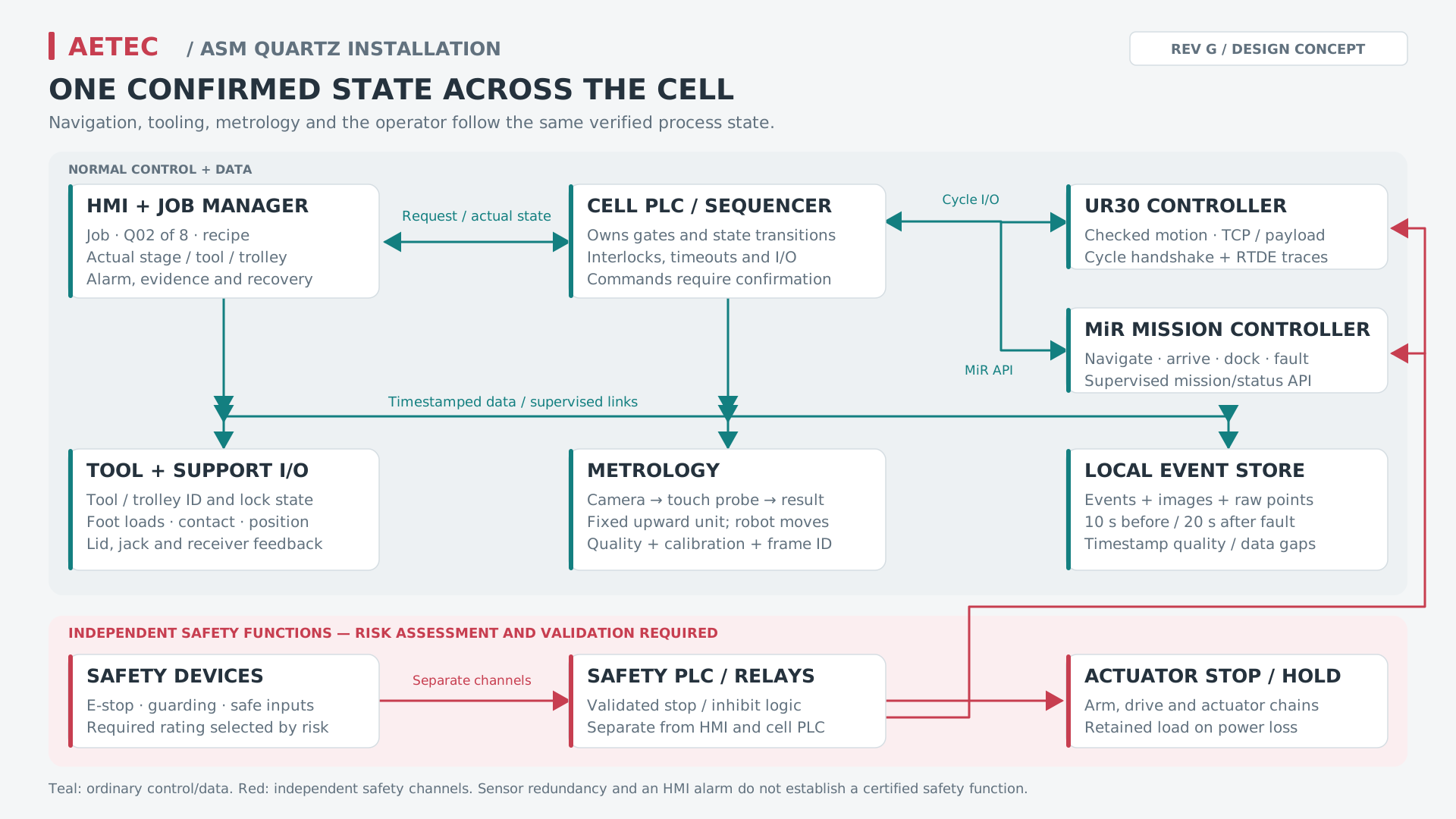
Select a job, machine, box and recipe. See requested and confirmed tools, calibration, fit quality, support condition and alarms. Requests go through the cell PLC.
The sequencer checks permissives, timeouts, latches and ownership. UR executes approved paths; RTDE supplies trace data. A supervised MiR REST adapter handles normal missions and arrival status.
Risk-assessed protective stops and motion inhibits use separate validated channels. The HMI mirrors their state. Camera/probe agreement and ordinary network data are not automatically safety-rated.
Link job, tool, trolley and calibration IDs to images, raw touches, transforms and sensor traces. Detect gaps or failed storage. Preserve the fault window; acknowledgement does not restart motion.
INTERACTIVE SUPPORT DEMO
This four-contact illustration assumes all vertical load is measured at known coplanar feet. Actual loaded wheels, stopping forces and structure must be included in the final model.
The 80 mm operating margin shown here is an example, not a released threshold. Do not re-level while holding quartz.
CONFIRMED TOOL DEMO
Assumes an empty tool and a supported nest. No real equipment connection.
OPERATOR INTERFACE / DIAGNOSTICS
Independent interactive software design demonstration. Synthetic signals only; no robot or safety-controller connection. A production historian needs separate implementation and validation.
Opening browser-local journal…
LIVE SEQUENCE / SIMULATED
FAULT WINDOW / 10 S BEFORE + 20 S AFTER
Reset only acknowledges. It never restarts the job. The buffer continues collecting post-fault samples while motion is held.
Job, machine, trolley, tool, calibration, timestamps, image references and raw probe points are traceable.
| Sequence | UTC time | Event | Trolley |
|---|
The demo stores events in this browser and keeps a bounded 10-second synthetic trace ring. Production design: local append-only journal, durable fault files, synchronized clocks, retention policy and a HOLD on mandatory logging failure.
Separate from the interactive 3D simulator. The recordings load only when requested.